What's New in Automation Studio™ P9.0
Once more, Automation Studio™ P9.0 - Professional Edition pushes the ‘Trade-Oriented’ concept implemented in the
software a step further, always with the same objective: achieve higher productivity with less effort. Designers,
test
and reliability specialists, trainers and maintenance technicians and engineers will all appreciate the new features
and functions and add them to their box of essential tools.
Contact us for a
Live Online Demonstration of the new features.

Request a Demo
*The availability of some of the new features is subject to the configuration of the purchased license.
Robotics Workshop
This new Robotics workshop of Automation Studio™ provides users tools to create and to
simulate
sophisticated robotic workcells. The workshop provides robot models that accurately
replicate the
dimensions and the functionalities of actual robots, enabling users to work with the
simulated robots in
the same way as the actual robots. The workshop also provides other robotic objects,
such as loads or
conveyors, allowing users to build their own production lines and check the interactions
between them
before the actual system can be built. Additionally, the workshop provides the capacity
to create
all-in-one co-simulations which integrate robots with other technologies in the
Automation Studio™
ecosystem (such as PLC), which will bring users to the next level of comprehensive
simulations in
Automation Studio™.
Pipe and Instrumentation Diagram Workshop
This new piping and instrumentation diagram workshop offers users an initial version of a
process
diagram editor.
It offers a library of symbols for the most frequently used components, such as pressure
and flow
valves, tanks, compressors and pumps, as well as exchangers.
Pipe editing and, more generally, the representation of symbols on diagrams, will follow
the rules of
representation recommended by the ISA 5.1-2009 and ISO 14617 standards.
Virtual didactic benches will be available for teaching exercises relating to level and
temperature
control.
Component Appearance
Following on from the improvements made for lines, cylinders and directional valves, it
is now possible
to change the visual aspect in simulation and editing of all other components. It is
possible to
visually identify and distinguish the mobile and fixed parts of components, their
activation states,
filling volumes and pressurised regions. Standards have been predefined, but users can
create their own.
These visual additions make it possible to transform a design diagram into a document
dedicated to
training or technical publication simply by changing the document standard.
Fittings Configurator
The realism of a fluid system simulation depends, among other things, on an adequate
evaluation of the
pressure loss caused by all the elements of the circuit. Hoses, pipe or tube ends, as
well as elbow or
T-type fittings for example, are often missing from the diagram or neglected or in the
digital model.
The fittings configurator allows fittings to be added to lines, adapters to be added to
components and
connectors to be added between elements without requiring additional symbols on the
design diagram. The
associated pressure losses will nevertheless be taken into consideration during the
simulation. The
addition of these components will, however, be reflected on the parts list (BOM).
While waiting for the release of the fittings manufacturers’ catalogues, the user can
configure the
fittings that are most frequently used in their systems.
Using STEP Files for Generic Components
Generic components for manifold blocks are represented with generic shapes (cylinders or
cubes). It
will now be possible to replace these generic shapes with STEP files chosen by the user.
Although many component catalogues are available, this addition makes it possible to
manage specific
components that are not yet in these catalogues.
Displaying Section Views in Technical Drawings
This new function will make it possible to define section views in the 3D environment and
make them
available in technical drawings. Once defined in the 3D environment, the creation and
updating of
section views is automatic.
The automatic creation of technical drawings will take into account the section views
defined by the
user.
Evolution of the Custom Component
The evolution of the custom component makes it possible to model multi-technology
components. In other
words, the component created will be able to handle multiple technologies. It will be
possible, for
example, to create an electro-hydraulic component compatible with the multi-technology
diagram editor.
In the field of processes, it will be possible to configure a component with several
types of incoming
and outgoing fluids, for example to create a distiller.
This development opens up numerous modeling possibilities, such as in the electrification
of mechanical
systems or in the process industry where it is not possible to create all possible
models.
Grippers
A new family of actuators is available in the pneumatic workshop : the pneumatic
grippers. These
actuators are most often used for pick and place applications. This new family offers
single and double
acting grippers with angular or parallel finger operation.
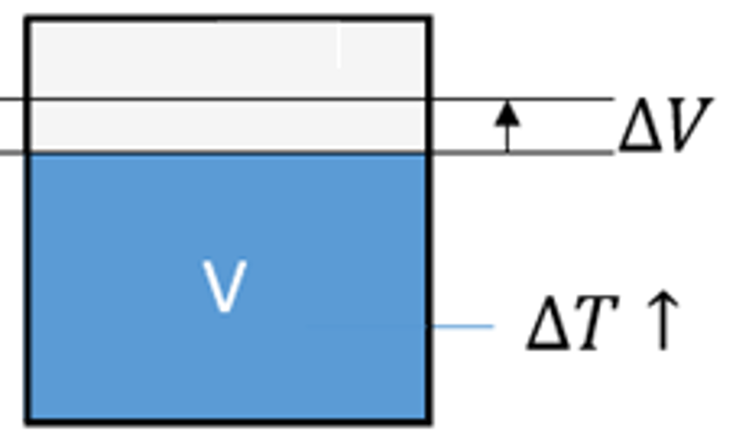
Oil Volume Variation
The variation in the oil volume based on the pressure to which it is subjected was
already taken into
consideration. With this new evolution, the influence of temperature on the oil volume
will also be
considered.
New Process Illustrated Component Library
A new library of illustrated components is available to extend the areas of application
of didactic
benches. Process components were added in order to be able to use volume control,
temperature control
and HVAC-type systems for training purposes.
New Language
The Python language has been added for creating scripts in Automation Studio™.
New Blocks
Additional blocks have been added to cover a wider range of modeling cases. Moreover,
some of these
blocks help streamline certain functions.
New Current Transformers
The new Current Transformers have two simulation models: the simplified model and the
advanced model.
The simplified
model has a limited number of parameters such as frequency, transformation ratio and
values not to be
exceeded. It
simulates, in addition to the transformation factor, the safety factor and the thermal
overload current.
If exceeded, an
error message is generated. The advanced model, more realistic, uses construction
parameters and
simulates the remanence
effect and the saturation effect.
New lights and lamps
The new lights and lamps have several simulation models that allow taking into account
the parameters
of voltage, power,
luminous flux and luminous efficacy.
Export to XML IEC 61131-10 format
Ladder diagram documents are now exported in XML format as defined by IEC
61131-10.
Multiple Translations
BOMs and reports now provide the possibility to display data in multiple
languages at the same
time. A new BOM and report field called “User Translated Property” can be
used to select a term to
translate and the language into which it should be translated. The text is
translated using the
translation manager database.
The translation field can be added multiple times so that any number of terms
can be translated
into as many languages as required.
Custom Component
Access to documents that define the behaviour, logic or symbol of a custom
component is possible
even if the component is grouped or assembled with other components. This
development allows, for
example, the declaration of failures in the behaviour of any custom
component from the illustrated
(educational) libraries.
Component Appearance
As has already been done for hydraulic components, it is now possible to
configure the appearance
in simulation and edition mode of pneumatic, mechanical and control
components. Different parts of
components can easily be distinguished, such as mobile or fixed parts, the
active or inactive
elements, fillable volumes and pressurized areas. Standards have been
predefined, but users can
create their own.
These visual improvements make it possible to transform a design diagram into
a document
dedicated to training or technical publication, simply by changing the
document standard.
Title Block Editor
This new feature allows any user to create their own title blocks. The title
block is drawn
directly on the diagram, making it possible to immediately see the result.
The title block structure is drawn using lines. The content can be simple
text, user-editable
text or text retrieved from configured application settings. All of these
elements can be added
very easily inside the title block frame.
A title block can consist of several frames. Each frame can be positioned
anywhere on the page or
automatically attached to a corner.
Modify the value of a dimension
It is possible to add linear and angular dimensions on technical drawings.
These dimensions can
be attached to predefined anchors or customized by the user.
Placing customized anchors precisely on a diagram using the mouse can be
difficult. It is now
possible to directly specify the value of a dimension or an angle.
Improved system for calculating the cost of a
manifold block
An estimate of the cost of a manifold block can be obtained by adjusting
parameters in the price
database.
2 tables have been added to this database. They now allow the user to enter
the machining time
per drill bit and per cavity type. This brings precision to the overall
calculation of the
manifold block cost.
Polygon, arc and curve shapes available for
technical diagrams
It is now possible to draw polygon, arc and curve shapes on technical
drawings.
Updated Residential Electricity Component Library
A new section with blueprint elements has been added to the residential
electricity illustrated
component library. This section includes outlets, switches, walls, doors and
more to draw a
completed electric blueprint of a house or apartment for training purposes.
Updated PID Blocks
The prebuilt PID control blocks have been revised to include a filter
coefficient on the
derivative branch, command signal output limits, and a back calculation
anti-windup on the
integrator branch.
New Components
- Added (thyristor, transistor, DIAC, TRIAC and optocoupler) and updated
components in the
illustrated library "Electrical
- motor control renewable energy".
- Updated the illustrated library "Electrical - DC electrical".
New Components
- Additions and updates of shaft-mounted speed and position sensors and
encoders: Potentiometric
Sensor, Resolver Sensor,
Synchro Sensor, Inductosyn Sensor, RVDT Sensor, Incremental Encoder,
Absolute encoder, 90° Hall
Effect Sensor, 120° Hall
Effect Sensor and Incremental encoder with direction of rotation port.
- We can plot A(θ), B(θ) and Z(θ) from the Incremental Encoder. By analyzing
these plots, we can
determine the motor's
direction of rotation based on the phase relationship between A and B.
Additionally, by examining
Z(θ), we can calculate
the RPM, as the Z pulse occurs once per revolution.
- We can plot and compare relative position calculated by the decoder to the
angular position of
the motor. We notice that
both signals match meaning that the decoder is working correctly.
Ability to Define Custom Material Names
The Automation Studio™ Manifold Workshop contains generic material names that
may not be suitable
for the application user.
It is now possible to define custom material and material finish names.
Dynamic Tables for Technical Drawing Title Blocks
It is now possible to define tables, attached to the title blocks of
technical drawings, that
automatically fill with project data.
The data can come from the part list or revisions.
Further improvements have been made in the title block editor.
Export Technical Drawings to DXF
The technical drawing and the production drawing can be exported in PDF and
DXF formats.
Additionally, the tables containing part lists, revisions, technical data or
machining operations
have been improved to allow modification of text fonts.
CETOP with Through Mounting Holes
The generic CETOPs available in the Generic Catalogue now contain the
“Through Hole” option for
mounting holes.
Dynamic Measurement System Improvement
Dynamic measurements make it easy to move elements in 3D.
The improvement concerns CETOP-type elements. It is now possible to take a
measurement and move
the CETOP from any of its sub-elements (Ports, mounting holes, locating
pin).
Robotics Workshop
Collaborative robots (Cobots) can now be simulated in Automation Studio™.
Users can easily put
them in a simulation work cell, program them, visualize their actions in 3D,
and analyze their
performances.
Stability and performance improvements are included in this new version of
the Robotics Workshop.
Improvements to the Cylinder Model
It is now possible to add cushioning to cylinders. Two methods of specifying
the cushioning are
available: simplified, or by curves. The simplified model uses a fixed
diameter of orifice and a
set length of application of cushioning on the first two ports of the
cylinder. The curve model
allows a variable cushioning curve to be added on each port of the cylinder.
The effects of cavitation on a cylinder that is included in a mechanism will
now be calculated.
A new model for calculating the effects of resistive forces on a cylinder in
a mechanism has been
developed. This model allows the simulation to run significantly faster when
there are friction
forces on a cylinder.
Variable Displacement Pumps and Motors
The control piston model for pumps and motors has been reviewed making it
more reliable and
adding configurable internal restrictions at the control piston ports.
Setting the Communication Speed
It is now possible to select the CAN bus communication speed to suit the
connected elements. The
following speed options are available: 100 kbit/s, 125 kbit/s, 250 kbit/s
(default value), 500
kbit/s and 1 Mbit/s.
New Distributor-control Solenoids
The distributor control solenoids have been revised to take into account the
types of solenoids
available on the market. The types of solenoids available are: DC ON/OFF, AC
ON/OFF, DC/AC ON/OFF
(with or without protection), AC/DC ON/OFF with rectifier, DC proportional
and proportional with
integrated analog control. We have also added the power reduction connector
and the proportional
solenoid controller.
Each solenoid has several simulation models: simplified circuit (simulation
from power),
equivalent circuit (simulation from resistance and inductance) and dynamic
model (taking into
account transients). The model takes into account the effect of temperature
which has an effect on
the current and the position.
New Symbols for Cable Representation
This version includes many new symbols to make it easier to represent cable
geometry on the
electrical diagram.
Power Balance and Temperature Calculation on DC
Machines
The power balance is automatically calculated in simulation on DC machines
(absorbed power, Joule
losses in the armature, Joule losses in the field, constant losses, useful
power and efficiency).
The machine temperature is calculated according to the cooling method (free
convection,
self-circulation, independent device mounted) and room temperature.
New search in online catalogues
The new version of Automation Studio™ online catalogues now allows advanced searches
based both on
keywords and on technical properties present in the catalogues. The technical data to be
searched can be
quickly defined and filtered based on manufacturers and catalogues, thanks to a new
user-friendly
interface.
New and updated manufacturers’ catalogues
Many Manufacturers' Catalogues have been added and updated. The new technical data allows
compatible
manufacturer components to be used within the Hydraulic Manifold Block workshop, and
enables direct
integration of the pre-configured and documented manufacturer components into your
Manifold Block in
Automation Studio™. Manifold compatible components are identified in the Catalogue
Manager.
- Argo-Hytos NEW
- AVENTICS UPDATED
- BUCHER Hydraulics SOON
- Cy.Pag UPDATED
- Dana Brevini Pumps & Motors UPDATED
- Danfoss MVB Valves NEW
- Danfoss Pumps and Motors UPDATED
- Hengli Cartridge Valves NEW
- Hengli Mobile Valve NEW
- HydraForce UPDATED
- Koganei UPDATED
- Parker Industrial Proportional Directional Control Valves UPDATED
- Parker Motors UPDATED
- Related Fluid Power SOON
- Sun Hydraulics UPDATED
- Weber-Hydraulik NEW
- Yuken Pumps UPDATED
- Yuken Valves UPDATED
Additional Manufacturers' Catalogue components are added and updated on a weekly basis.
New machining parameters list and export
The list of all machining operations can be generated once the 3D manifold design is
completed. The
types of machining operations are described according to industry standards. Each
parameter can be
directly modified from the list, with the values being automatically updated on the 3D
layout and in the
technical drawings.
Interface Automation Studio™ with Mastercam®
This list of machining operations is exported as an XML file. This allows direct transfer
of machining
information from Automation Studio™ to CAM software to help streamline production.
Generic orifice plug
An orifice plug component with various configurable sizes has been added to the generic
manifold
catalogue.
Cavity thread visualization
Cavity threads are now represented visually in the Cavity Manager and in the 3D Manifold
Layout.
Spotface / counterbore merge
It is possible to remove a spotface from a cavity if the cavity already contains a
counterbore.
Own hole closure catalogue
Default hole closure plugs are available in the application. It is now possible for a
user to have
their own hole closure catalogue.
Manifold auto-create feature
Sorting parameters for “Auto-Create” routing solutions can now be customized.
Technical documents
Improvements have been made to the technical and production drawings, including the
ability to add
arrows at the end of a line, add machining information and group callouts. The machining
parameters can
be displayed as tables on the production drawing document. The new version allows them
to also be
displayed as callouts around the views.
Block cost calculation system
A new cost calculation system was added. All the data relating to the manifold block are
exported to an
Excel file (part list, machining parameters, diagrams, etc.). The user can then create
their own block
cost calculation formulas based on the actual block data.
New manufacturer cavities
Additional manufacturer cavities have been made available for use in the manifold
workshop.
- ARGO-HYTOS
- Bosch Rexroth
- Bucher Hydraulics
- Dana Brevini
- Danfoss
- Delta-Power
- Eaton
- FEMA
- HAWE Hydraulik
- Hengli Hydraulics
- HYDAC
- HydraForce
- Oilgear
- Parker
- Related Fluid Power
- Sun Hydraulics
- Wandfluh
- Weber-Hydraulik
- Yuken
New GRAFCET module
The new GRAFCET module fully complies with the IEC 60848 standard and allows programs to
be edited and
simulated. Our GRAFCET module allows the usage of different input event types, output
modes (continuous
and stored modes), structuring (partition, forcing, enclosing, macro-steps).
New SFC module
The new SFC module fully complies with the IEC 61131 standard and allows programs to be
edited,
simulated and, later on, exported. Conditions and actions can call the project's ladder
diagram networks
(LD). The module supports structured text language (ST). It also takes into account the
different action
qualifiers, as well as control actions with or without a final scan.
New connector builder
The new builder allows bills of materials and images for 2D and 3D diagrams to be
configured for
connectors. New pin, socket and connector symbols have been added.
Virtual Trainers
Automation Studio™ offers a series of ready-to-use training benches which demonstrate how
to design
technical functions by connecting components from different technologies, by programming
automated
machines to activate operative parts. The DIGITAL TWIN of your hardware trainer can be
easily created.
Flexible links have been implemented to complement the 2D CAD illustrated libraries in
reflecting the
visual aspects of hardware trainers for both fluid power and electrical technologies.
Multitechnology Diagrams
The addition of Multitechnology Diagrams makes it possible to group together, on the same
page,
hydraulic, pneumatic and electrical components as well as circuits made in a ladder
diagram and
human-machine interface elements, recreating a realistic digital twin.
Library of illustrated hydraulic components
This library allows users to create comprehensive illustrated hydraulic circuits to meet
educational
and training needs.
Library of cutaway pneumatic components
To meet the needs of training departments, this library has been added to create
pneumatic circuits
that display the internal workings of the most commonly used pneumatic components.
Zoom increase
The zoom can go up to 4000% so that objects can be drawn more precisely for animation
purposes.
Visual usage indicator
Visual cues have been added on various components, which make it easier to identify, for
example, which
cylinders participate in a mechanism, what is the source of the electric charge and its
operating
quadrant and in which direction the mechanical power is transmitted.
2D animations
This enhanced visual interface improves the user experience when creating 2D animations,
all visible in
one place. A preview of the animations will help you validate the expected behaviour.
Quick line type selection
While drawing a conduit or a wire, or after selecting it, you can modify the type of link
from a list
which is displayed instantly.
Dynamic adjustment of actuator forces
To make initial testing easier and quicker, and to eliminate the need to define forces in
advance,
forces can be applied to the hydraulic and pneumatic actuators in simulation by clicking
on them while
the simulation is running.
Component categories
To define specific naming rules or particular appearances based on the type of component,
the component
categories have been developed. Each category can have a unique set of attributes that
differentiates it
from the other categories.
New options for colouring electrical wires in simulation
You can now choose the criterion for colouring electrical wires in simulation, based on
thread type or
globally. In addition to the type of current, one can choose colours according to the
level of voltage
or the level of current. You can also keep the appearance that the wires have in
editing.
Orbitrol
The Orbitrol model has been redesigned with the aim of addressing all identified usage
scenarios.
New catalogue of mathematical blocks
The catalogue of mathematical blocks will open the possibility to create custom and
adjustable
components, objects, functions and systems from mathematical models to drill down into
the sub-component
level.
You can now choose the behaviour you want for the components in your circuits during
simulation: by
performance curve, mathematical models of your own, or both. This catalogue gives an
unmatched
flexibility to Automation Studio™.
New block components
This library is enriched with mathematical blocks allowing matrix calculations as well as
complex
number operations.
DC machines
New DC machines (motors and generators) operate in all four quadrants and have mechanical
connectors.
This includes permanent magnet, separately excited, series wound and shunt wound.
Operational amplifiers
The new operational amplifiers make it possible to carry out the basic assemblies.
Three phase induction motor with neutral, squirrel cage
To complete our range of motors, we have added the asynchronous motor with neutral.
Improved synchronization in certain cases where internal and external
cosimulation is used.
Component Hyperlink Zoom
The zoom level can be set independently for each document. This zoom level is
used when clicking
on a hyperlink (BOM, jump, etc) that points to a component on the document.
The zoom option can be accessed in the properties of the target document.
Line colour in simulation per line type
The simulation colour as a function of pressure/flow/speed/temperature for
hydraulic and
pneumatic conduits can be set independently for each line function.
For example, different pressure thresholds can be set for working lines vs
pilot, return and
drain lines.
Text list variable
It is possible to create variables that consist of lists of custom text.
There are no
restrictions on the type of text that can be used for elements in the list.
This type of variable allows discrete lists to be created.
Breather
It is possible to connect a breather to any of the top ports of a custom
reservoir. This port
must be declared as pneumatic.
It is thus possible to regulate the air pressure in this type of tank, either
by directly
connecting a breather or via a pneumatic circuit.
New illustrated electrical component library
A new illustrated component library has been created to extend the capacity
to build digital
twins. French residential electrical components have been added so that
unambiguous residential
electrical circuits can be drawn visually.
Step by Step Mode
The increment used by Step by Step mode can now be modified. The simulation
will advance by a
step which can be set by the user.
Dynamic Measurements
Dynamic Measurements are automatically displayed on the 3D Layout as soon as
a component or a
drilling is selected and/or moved. This makes it possible to quickly
position and adjust any 3D
objects on the block. The displayed measurements are the position relative
to the 4 edges of the
block, the depth of a counterbore and the datum for a buried component. For
the drillings, the
depth and the angles are also displayed.
The user can directly edit the displayed values by clicking on them and
modifying them.
GD&T Font (Geometric Dimensioning and
Tolerancing)
The GD&T (Geometric Dimensioning and Tolerancing) font is now available
in technical drawings
and can be used to draw special characters for the dimensioning information.
Representative Machining Callouts
This new feature is integrated in the automatic Production Drawing creation.
Special
configuration options have been added.
System Specifications
Using functional groups, you will be able to group components that are part
of a specific
function and sub-function of your machine (such as: primary system,
secondary system, auxiliary
system, cooling function, etc.).
For each of the functional groups identified, you will be able to define
different operational
modes with activation and termination conditions to measure performances.
You will be able to quickly obtain the current performances and validate that
all design criteria
of your system have been met through simulation.
Multiple Directional Valve Flow Curves
The flow through an internal channel can now be set as a function of the
value of several
differential pressures measured at its ends. This improvement of the model
makes it possible to
perfectly simulate the performance of manufacturers' distribution valves
whose specifications
cover a wide spectrum of working conditions.
Pressurized reservoir
In the hydraulic reservoir builder, it is possible to define ports on the
upper surface of the
reservoir as pneumatic ports. The simulation of enclosed air will cause a
variation in pressure
based on the volume of oil. A pneumatic system can also be connected to
regulate this pressure.
Line jump with reservoir symbol
This component helps with representation and simulation of multiple returns
to case drain within
a pump or motor assembly, among other things.
True RMS
The measurement of true RMS values and frequencies of electrical signals have
been improved and
can handle all types of signals.
Pneumatic pilot
Directional valve pneumatic pilots take negative pressure (vacuum) into
account in the
calculation of the force applied to the spool.
Diagnostics
New diagnostics have been developed to help understand circuit design. The
first diagnostic
identifies any components that have been created using the custom components
module. The second
diagnostic identifies black box components or components that have a
modified symbol.
Project Overview
In the project creation dialogue, a preview zone gives a quick look of the
project content. The
documents of the project can be scrolled through.
Hyperlinks
The hyperlink creation dialogue has been made more user friendly by providing
a list of the
available protocols, the required syntax and a brief explanation of the
required fields.
Catalogues
When searching for a catalogue component equivalent to a component on the
schematic, it is now
possible to search either the online or local catalogues. This makes the
online catalogues even
more useful.
New Electrical Illustrated Component Library
A new illustrated component library has been created to extend the
capabilities to build digital
twins. One-Line electrical components have been added in order to be able to
draw electrical
transmission network circuits explicitly and visually.
Additionally, the following illustrated libraries are also available:
pneumatic, PLC, DC
electrical, renewable energy, residential electricity, hydraulic
cross-section, and more.
New Electrical Symbols for Aeronautics
A new electrical symbol library has been added. It allows electrical circuits
to be represented
in compliance with the standards used in the aeronautical field. In the
Automation StudioTM
electrical schematic editor, these symbols are compatible with documents
using the NEMA standard.
Component Frame
Each component or assembly of components can be framed without adding drawing
elements.
The frame is manually adjustable and customizable; width, height, thickness,
color and line type
can all be modified.
Online Manufacturers’ Catalogues
Manufacturers' Catalogs are now available online. There is no longer a need to manage
catalogue files
or worry about updating them. The web Catalogue components are always up to date. Simply
drag the
desired components from your browser onto your Automation Studio™ schematic to use them.
User-friendliness
Shortcuts giving access to the layout of the current document as well as to its drawing
scale have been
added in the “Home” tab, “Documentation” group.
Optimization
Optimizations to generate more compact blocks.
User-friendliness
Addition of a dialogue box confirming the unit system selection when generating a new
manifold block.
Custom Component Edition
To increase efficiency, the user can now edit the source circuits of a custom component
without having
to return to the original project. The user will be able to modify the symbol and its
animation, its
logic and behaviour circuits.
To meet the needs of training and technical publications departments, new line
highlighting attributes
have been added. The highlighted line endpoints can be flat or rounded, the corners can
be square,
rounded or chamfered, and the segments defining component connectors can be highlighted
or not.
Appearance of Fluid Components
To meet the needs of training and technical publications departments, directional valve
positions can
be highlighted in edition and simulation according to their activation status. A library
of additional
objects can be provided on request in order to complete components that do not yet
support these
highlighting standards.
Appearance of Fluid Lines
To meet the needs of the training and technical publicatons departments, new appearance
attributes for
each line type have been added. Highlighting can now be activated in simulation, can
support patterns,
and can be full or sectional.
Naming Rules
The naming rules are enhanced with new attributes. The user can display the dimensions in
fractional
form in the names of the lines, select the unit system, the precision, etc. The
available variables have
been organized to more clearly indicate thier use.
Export in Simulation Mode
To meet the needs of training and technical publications departments, it is possible to
export circuits
in a graphic format while the simulation is running.
Manual Override With Detent
Directional valve command to represent a manual override with detent groove, according to
ISO 1219.
Directional Valve Springs
An option has been added to adjust the spring compression screw during simulation.
Directional Valve Power Curves
An option has been added to define the power curves of a directional valve from the
differential
pressure or the inlet pressure.
Downstream priority pressure compensator
This component is designed to be used downstream of an orifice as a pressure compensator.
When used to
maintain a pressure differential on an upstream orifice, this valve can maintain a
constant priority
flow regardless of the downstream load.
Upstream priority pressure compensator, with static load sense
Upstream priority pressure compensator, with static load sense. This valve is intended to
provide
priority flow in the required amount while allowing excess flow to be used for auxiliary
functions and
maintaining a constant pressure drop across the control flow orifice, regardless of the
load pressure.
Upstream priority pressure compensator, with dynamic load sense
Upstream priority pressure compensator, with dynamic load sense. This valve is intended
to provide
priority flow in the required amount while allowing excess flow to be used for auxiliary
functions and
maintaining a constant pressure drop across the control flow orifice, regardless of the
load pressure.
The dynamic load sense feature generally provides a better response time. Additionally,
it increases the
spring differential on the control flow orifice by a ratio that depends on the orifice
sizing.
Viscometer and Density Meter
A measurement component has been added in order to access the measurement of the
kinematic viscosity as
well as the density of the oil in a node of the circuit.
Proportional Pressure Regulators
Models are made sensitive to back pressure.
Coolers
An option has been added to define the dissipated power according to the inlet
temperature, the outlet
temperature or the average of these 2 values.
Liquid Collector Exhaust Pressure Type
This component uses pneumatic pressure and flow to collect and reuse hydraulic fluid that
has leaked
into the system.
Lubricator
The addition of a lubricator, which will allow constant and automatic lubrication to the
correct level,
is a necessity for most pneumatic components to work correctly and have a satisfactory
life span.
Curve Modelling Restrictors
Pressure drops modelled by performance curves as a function of flow rate and variable
opening - for air
with simplified pneumatic modelling.
Block Components
New block components have been added to handle matrix operations and complex numbers.
2-Quadrant Curves in the Electric Motor
Added a two-way model. A new simulation model that takes into account the Torque-Speed
characteristic
Curve in the forward and reverse rotation has been added. In addition, a motor with 2
mechanical shafts
is now available in the library.
4-Quadrant Joystick
Joystick to generate 4 control variables.
Temperature Generator
A slider was added to make it possible to change the temperature during the simulation.
Environment Variable Generators
Components with temperature or light as a simulation variable now use the environment
variables of the
essential subdivision where the component is located.
Lack of current or inrush brake
Asynchronous motor 6 connectors
Transistor
Behavioural improvement. A capacitor has been added to stabilize the voltage between the
collector and
the emitter and between the drain and the source.
Ladder for Mitsubishi MELSEC iQ-R Series PLC
Hydraulic Manifold Block Workshop
Create and edit manifolds in Automation Studio™ with the new Hydraulic Manifold Block
workshop.
An Auto-Create function can quickly propose up to 100 manifold solutions based on your
Automation
Studio™ schematic and set constraints. You are then able to tweak the proposed designs
to your
liking.
Take pressure and flow measurements at any point in time during simulation.
New & Updated Manufacturers' Catalogues
Many Manufacturers' Catalogues have been added and updated. The new technical data allows
compatible
manufacturer components to be used within the Hydraulic Manifold Block workshop, and
enables direct
integration of the pre-configured and documented manufacturer components into your
Manifold Block in
Automation Studio™. Manifold compatible components are identified in the Catalogue
Manager.
- Automation Studio™ Electrical - Variable Frequency Drives NEW
- CKD Corporation SOON
- Continental Hydraulics Valves NEW
- Cy.Pag. NEW
- Danfoss Orbital Motors UPDATED
- Doosan Mottrol NEW
- Eaton Sectional CLS & CMA Mobile Valves UPDATED
- Humphrey Products NEW
- IMI Precision / Norgren SOON
- Koganei UPDATED
- Linde Hydraulics UPDATED
- Mitsubishi Electric SOON
- Shanghai Guorui Hydraulic Technology co (GRH) POWER Valves NEW
- SMC Pneumatics NEW
- Tecnord SOON
- Wandfluh NEW
- Zhejiang Gaoyu Hydraulic Machinery Co Ltd NEW
Additional Manufacturers' Catalogue components are added and updated on a weekly basis.

Online Manufacturers' Catalogues
The Automation Studio™ Web Catalogues lets you drag & drop components directly from
the web browser
interface to your Automation Studio™ schematic. These components are always the most
up-to-date version.
Therefore, there is no need to locally manage multiple manufacturers' catalogue files.
The Web
Catalogues for Automation Studio™ will be made available shortly after the release of
Automation Studio™
P7.
New Hydraulic Components
- Planetary gearboxes
- Differentials and torque converters
- Separate control surface valves
- Pressure compensated flow dividers
- Jumps with label frame
Improved Hydraulic Components Simulation Models
- Hydraulic motor plates can now have a limited stroke
- Added an exchange surface area for the external dissipation of hydraulic heaters
- Improved curve tracking in pressure regulators
- Pressure compensated flow dividers
- Improved manual directional valve commands
Support of Transmission Shafts in the Mechanism Manager
The Mechanism Manager now accepts rotating drive shafts. This implies that all rotating
elements, such
as hydraulic, pneumatic, electric motors and gearboxes, etc., can now be simulated in
the Mechanism
Manager.
New Pneumatic Components
- Compressors
- Vacuum generators
- Vacuum cups
- Normally closed flow sensors
Failure Mode, Effects and Criticality Analysis (FMECA)
Quickly obtain and communicate system failure information, thanks to the new FMECA module
of Automation
Studio™. It is based on, but not limited to, [IEC 60812] Failure Modes & Effects
Analysis. This can
greatly reduce troubleshooting time and increase system reliability.
Renewable Energy Custom Library
The new Renewable Energy library is made with illustrated components. It enables to
create and simulate
circuits with look-alike components from real-world applications. Some components even
animate during
simulation, creating an optimal experience for training activities.
PLC Custom Library
This library was created to enable trainees to actually wire up the PLC (Allen Bradley,
Eaton, Koyo, LS
Electric, Mitsubishi, Omron, Siemens, etc.), write the Ladder Logic and run the
simulation to see the
inputs and outputs being triggered on the PLC according to their ladder diagram.
DC Electrical Custom Library
This illustrated library is intended for DC electrical circuits. Components can be
connected directly
or by using the breadboard to create and simulate your circuit.
Residential Electricity Custom Library
Trainees can now quickly build residential electrical circuits using common components
which they are
familiar with.
Hydraulic Cross-Section View Library
Create your circuit using hydraulic components with a cross-section view that is animated
during
simulation. Trainees can now quickly visualize the flow movement in the circuit.
Hydraulic Cylinders with Load Custom Library
This custom library allows to quickly vary the cylinders load during simulation and
instantly see how
it affects the system.
Terminal Strips Builder
New terminals with jumper channels management of different categories were added:
- Feed-Through
- Ground
- Feed-Through with Ground
- Knife Disconnect
- Disconnect
- Sensor / Actuator
- Fuse Holder
- Distribution Blocks
Simplified terminals are still available. The new builder allows complete management of
the terminal
strips, including the accessories management and the part numbers. Terminal strip export
and import
functions are also available.
New Semiconductor Devices
New semiconductor components have been added to the Electrotechnical library, such as:
- Bipolar Junction Transistor (BJT)
- Junction Field Effect Transistor (JFET)
- Metal-Oxyde-Semiconductor Field Effect Transistor (MOSFET)
- Thyristors
Thyristors, bipolar transistors and field effect transistors have been introduced. The
thyristor can be
controlled by a variable or by an external circuit and the transistors have been
designed to operate in
both switching and amplification mode.
Improvement of the Battery Component
- The ageing effect on the battery capacity is now taken into account
- OCV hysteresis effect is taken into account by differentiating OCV vs SOC curves
during charge and
discharge
- New advanced model taking into account the voltage transients' behaviour during
charge and discharge
- Predefined battery parameters for the different available battery types
AB-500 and AB-5000 Compatible Functions and Addresses
These new libraries are an update from our original library that did not include all the
major
functions. These two new libraries enable you to create control circuits using addresses
(AB-500) or tag
names (AB-5000).
Additional Math Block Components
Adaptors in (math) blocks enable the creation of complex behaviours for fluid power and
electrical
components.
New Discussion Forum
Many customers want to share their schematics with other parties or simply share their
experience. The
new Forum allows access to demonstration files, custom libraries and other information
that can be
helpful to your applications. We hope that you will also share your experience with
everyone. If you
don’t have an account in the Forum, register here
Virtual Systems Using Unity 3D
Virtual systems created using Unity 3D allow for a training experience with a high level
of realism.
These systems can be controlled within Automation Studio™ using Electrical Controls,
PLCs and/or
Sequential Function Chart. Access the Forum to download the files and procedure to
install the Unity 3D
models. New virtual systems are frequently added.
Online Help
You can now access Automation Studio™ help documentation online. The online help
documentation is
constantly improved and updated based on users' support cases and feedback. Also, the
software
installation file size is reduced.
Mouse Options Configuration
The new mouse button configuration menu allows users to set their desired mouse buttons
behaviour in
Automation Studio™.
Smaller Simulation Pace
New simulation steps of up to 1 micro-second are available to allow finer simulations.
This feature is
particularly useful to simulate high frequencies phenomena (up to 100kHz), especially in
the electrical
workshop.
Conservation of the Internal Identifier of a Component When
Replaced
Component internal identification can be maintained when replacing the component. This is
useful for
systems that have a unique identifier for each component.
Other Customer Requested Improvements & Bug Fixes
- Performance improvements
- Fixed the radial speed variable of the transmission power units
- Fixed discrepancies of the output pressure value of the "Pressure and
Temperature Flow
Control" component
- Fixed the flexible lines acting as a plug after a while in simulation
- Fixed the behaviour of unloading valve with check and drain
- Changed the image shown in the component properties of the
"Bidirectional Motor with
Shaft"
- Fixed the Curve Export API not exporting all curves
- Fixed an incorrect pressure at port 2 of the pneumatic "Remote Pressure
Reducing
Valve" component
- Fixed unhandled exception error in PLCs when the '&' character was
inserted in the
description
- Fixed BOM order changing when a model is saved
- Fixed an issue with the BOM and lines when exporting to PDF
Manifold Block Workshop
New features are available with SR1 improving your experience during the
design, documentation
and simulation of your manifold blocks:
- Improvement of routing algorithms and in particular those of oblique
channels;
- Addition of CETOP-type components and interfaces in the generic
library;
- Ability to create a custom title block;
- Revision table available in the technical drawings;
- Customization of the number of decimal places that can be displayed
on technical drawings;
- Improvement concerning the dimensions on the technical drawings
(offset, movement);
- Ability to adjust the position of the shapes on the cavities of the
generic components.
Installation and Circuits
The limit of 30 types of lines in installation circuits has been raised
to better meet user
needs.
New Hydraulic Components
- Instant temperature regulator;
- Mechanically activated check valves;
- Sequence valves normally open, with internal drain and external
drain;
- Cartridge valves normally open;
- 3-way sequence valve normally closed;
- Restrictive pressure compensator positioned downstream.
Improved Hydraulic Component Simulation Models
- Addition of a pressure drop curve in the flow transducer;
- Improvement of the proportional flow regulator.
Mechanism Manager
Support for mechanically linked jacks in the mechanism manager.
Troubleshooting Module
- You can now declare several parameters for the same failure, thus
being able to model a
minor, moderate or major failure.
- You can now report unidirectional internal leaks.
Wire Management
Wires can now be individually set as perfect without changing the global
setting.
Ease of use
- A dialogue box prompts for the choice of unit during the assignment
operation to facilitate
the interpretation of the value of one variable assigned to another;
- It is possible to hide the identifier of dynamic measuring
instruments.
Fluid and Line Manager
Pipes and wires whose properties are used by the simulator are displayed
in blue.
Managing properties’ preferences is also possible.
Configuration Export
Software settings can now be imported and exported for uniform computer
configuration.
Illustrated Libraries
A new command opens illustrated libraries directly from the application.
Project Manager
The page numbers of documents can be displayed in square brackets in all
dialogue boxes that
show the list of documents, such as the Project Explorer.
Video Recording
The video recording tool offers the possibility to replay its video to
validate the content, to
save it or send it immediately after creating it.
Hyperlink
When a hyperlink type custom property is displayed on the diagram, it
becomes clickable.
Service Release Number
The service release number for your version has been added in the
dialogue box opened by the
"About" command.
Ticket Request
A command has been added in order to be able to request assistance from
Automation Studio™ in
the Support tab. It will then be sent automatically to a support agent.
Viewer
Export your Automation Studio™ projects in a brand new format suitable
for the free Automation
Studio™ Viewer. This file format removes properties from documents and
components that the
designer does not want to share. This file format can only be opened
with Automation Studio™
Viewer, making it easy to share while maintaining a high level of
confidentiality.
Electrotechnical inputs / outputs
These new black box components (Universal input, Universal output, Input
converter and Output
converter) make it possible to efficiently model and simulate
Electrotechnical components that
have versatile inputs and outputs such as controllers, sensors, etc.
Library of preconfigured PLC Cards
A new specialized library of PLC input and output cards offers you the
possibility to quickly
expand your range of teaching materials for educational activities in
automation
Additions in the Hydraulic Block Manifold module
Improvements have been made to automatic routing, options for displaying
dimensions on
technical drawings and automatic management of stackable CETOP valves.
It is also possible to
decide whether the routing algorithm can use oblique channels or not in
the case of a
"Counterbalance valve" type assembly.